The 1/100th scale model of Wimborne Minster in Dorset, UK, is finally finished. A prolonged printing process, delivering models to be painted at the site finally came to a conclusion in late Summer.
Some nice coverage here from BBC News.
High Quality 3D Printing Services
The 1/100th scale model of Wimborne Minster in Dorset, UK, is finally finished. A prolonged printing process, delivering models to be painted at the site finally came to a conclusion in late Summer.
Some nice coverage here from BBC News.
Just 5 minutes ago a friendly chap from DPD came to collect my CR10S-Pro and return it to Amazon. Why? Read on.
Earlier in the week the printer had completed a print – one that was pretty close to perfect in every way – and I turned it off for the night. The next morning I switched it on to start another – a print that was already on the SD card, prepared in Simplify3D using the exact same profile as the previous one – and at the initial “centre” calibration the printer does moving home to print the purge line the nozzle buried itself into the bed and the printer made that jammed motor sound we all hate to hear. It was exceptionally lucky I was still next to the printer when it happened as on any other day I would have been in another part of the building and may not have noticed this state for some time.
So what’s gone wrong? My first thought was that the bed sensor had failed but testing by raising the z-axis and allowing it to start to lower showed that the sensor was triggering, or at least that the LED on top was lighting/going off appropriately when something came near, but the z-axis just kept on lowering. The simple explanation would be that the sensor was being ignored, which might suggest a broken cable or loose plug, but given that the sensor had power this seemed unlikely.
The worst part of the problem though is actually in the design of the firmware. With the sensor or firmware clearly having a problem sensing the bed my next thought was “OK, let’s just go with manual levelling”, but with the CR10S-Pro there’s no way to do that. Even choosing the levelling top-level menu item, not even any actual action, causes the printer to carry out this centre point calibration and, of course, this caused it to crash into the bed so I could do nothing, at least not without taking the thing apart.
So why didn’t I try to fix it? For a start it was only 6 weeks old and had accumulated no more than about 30 hours of printing. A loose screw is one thing, what appears to be a hardware failure after such a short time is another. More importantly there are other issues with the CR10S-Pro that strongly indicate the machine has been rushed out of the factory.
I’ve mentioned in a previous post that the filament path from the reel to the runout sensor causes stress and scraping of the filament. OK, it was solved by a couple of simple 3D printed parts I made up, but this problem would have been obvious to anyone that actually watched the printer working so you’ve got to ask how much “burn in” this model actually had.
Then there’s the dust on the rollers. I saw this building up after just a couple of prints and it continued to be a problem thereafter. This has to be wear on the rollers and given the amount of dust being produced I can’t see how they’d last more than 6 months without wear introducing inaccuracy in the extruder carriage movement.
Lastly, but by no means least, there’s the bed sensor itself. This is a capacitive sensor, one that detects practically anything, not just metal, and capacitive sensors are known to be highly susceptible to changes in environment like temperature or humidity. Not only this, but I’d already been concerned that each measurement cycle of the automatic levelling process produced different readings from each point, even if carried out one immediately after the other. I’d seen different prints using the same profile from S3D produce dramatically different first layer quality after the auto-levelling process, it really did seem like luck of the draw.
All in all, after less than 6 weeks of ownership and really quite light printing (compared to my Prusa that runs virtually every day, all day), I’d spent way too much time trying to get the CR10S-Pro working properly. The decision to send it back was relatively easy to reach.
In many ways it’s a shame. The build quality was generally excellent, the full-colour screen nice to use and the menu system really quite good and easy to understand. When it worked well, the printer produced some outstanding prints – far better than my other older machines – but mine was just too darn flaky. When version 2 comes out and there’s evidence these problems have been addressed, the CR10S-Pro will make a fine value machine, but I’d hesitate to buy this first version.
It’s been just over a week now since I received my Creality CR10S-Pro and, perhaps inevitably, I’ve hit my first real snag. This morning halfway through the first layer of a print there came the horrible sound of a printer in distress and by the time I could hit the power button the nozzle had buried itself into the print bed.
Everything looked fine from the front, although I did notice some
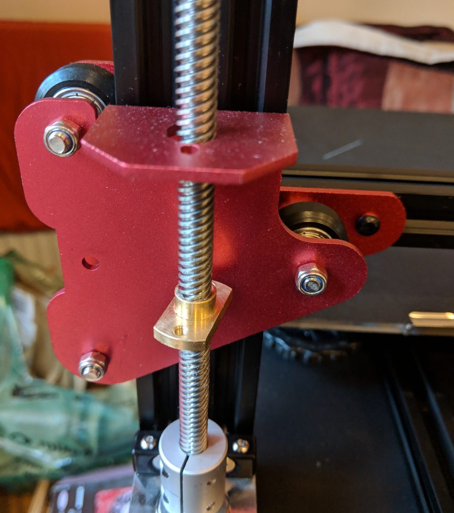
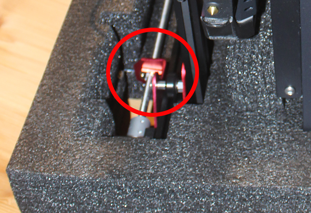
The brass lead-screw guide on one side was flapping around in the breeze. A (fairly) thorough search of the area revealed no random unclaimed screws on the floor or desk so I can only assume this part was never screwed into place. Regrettably, none of my unboxing photos have a clear shot of this side of the frame, all I have is this shot where the area in question is out of focus (not, for once, because of my poor camera work but because it’s in the background).
It’s really not possible to see if there are any screws in place, especially as I don’t know how far, if at all, they should protrude beyond the bottom of the guide, but to my eyes that brass piece doesn’t look parallel to the mounting plate, which it would have to be if both screws were in place and tight.
A check of the other side revealed that while this had both screws in place, they were loose so the z-axis was held in place virtually by its fingernails.
It’s really rather annoying that I don’t know the state of either of these guides upon first build. IF this loose fitting/missing screws was the cause of the z-axis crash (and it seems an incredible coincidence if it wasn’t), then it seems odd that the first test print and about half-a-dozen subsequent prints have all been fine. More worrying is that the second layer of my reprint following my repairs (luckily I had some spare screws to fix the unattached guide in place) and recalibration is still looking a little “wavy” whereas previous prints had all been perfect.
The residue on the x-axis rollers looks like it might be rubber “dust” from where the rollers are wearing on the metal cross-piece. Hopefully this will be a one-off because they’re new and not continual wear because there was a relatively substantial build-up and if that’s just a week or so of printing these rollers will have worn away in a few months.
I’ll continue to look for why the layers seem inconsistent now but if you’re considering a CR10S-Pro please do check ALL the screws and fittings you can see and make sure everything is tight that should be tight and nothing seems unattached!
The Creality CR10S – Pro has come along at a perfect time for me. I’ve been looking for an additional FDM printer for some time and had been attracted by
Unboxing
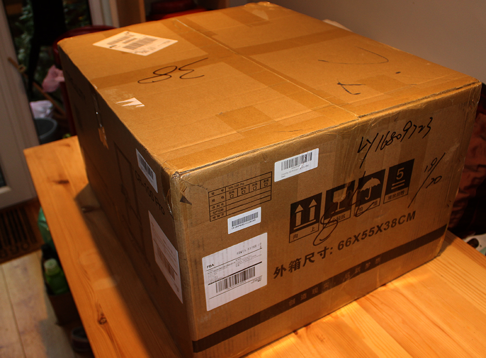
The box is as large as you’d expect for a printer of this size & type, though not especially heavy. It looks huge here sat on the kitchen table (the only place I had room to do the build!), but a lot of that is the packaging.
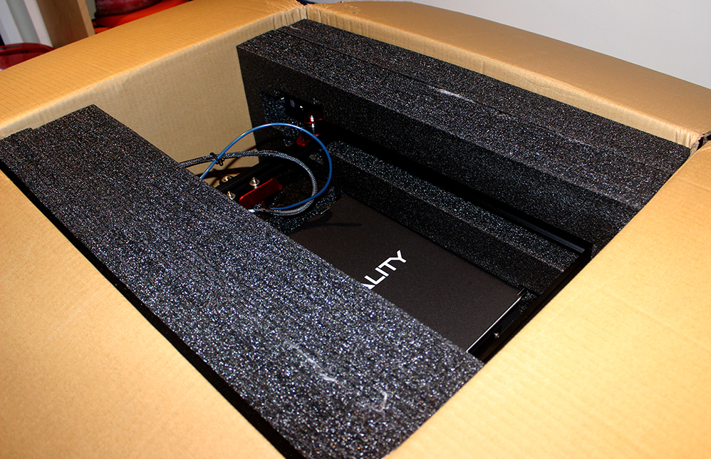
Opening the box reveals a vast empty space in the centre and the thick padding either side and to the top and bottom, with the two main printer parts comfortably held in the centre. There’s no way to remove anything individually from the box, you’ll have to lift the entire interior packaging and all from the box and onto your work surface and this will probably be a lot easier with a second pair of hands, although I did manage on my own.
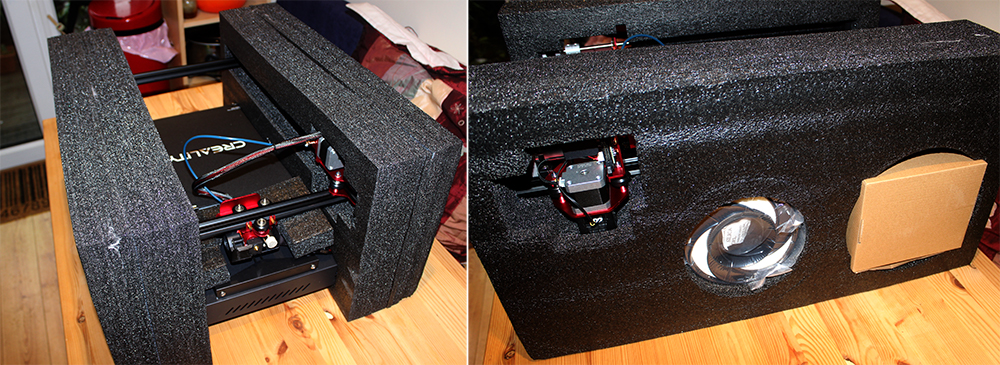
On one side of the packaging is the (very!) small reel of PLA filament (mine was a translucent white) and a box containing various tools, leads, screws and so on. Remove these and put them to one side.
I found the easiest way to removing the printer parts from the packaging was to turn the whole thing on its side with the side that had contained the reel and the box facing downwards.
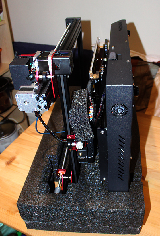
The top half of the packaging then comes away fairly easily, you can remove the small piece of extra packing (seen above in the centre of the photo) and can ease first the upper frame (to the left of picture) out, placing it somewhere safe, then the base itself.
![]()
A key issue for any FDM printer is bed adhesion; prints must be firmly attached to the bed during the print process to ensure they don’t move but they also need to be easy to remove without damage once the print is complete. There are countless bed surfaces, tapes, glues and tricks that printer manufacturers and printer operators use to achieve this combination of stickiness and removability and each method has their own fans and detractors. I’ve been looking for a good solution specifically for PETG/CPE printing as, for me, this is the material that causes the most grief.
PETG is unlike most FDM filaments in that it’s really too sticky. Print PETG directly onto glass or a PEI bed surface and you’re likely to find the finished part is forever welded to that surface. After some experimentation, I’d settled on using Scotch Blue Tape as the base for my PETG prints, sometimes combined with some Elmer’s Purple glue or 3DLac spray for particular models prone to first layer problems and/or warp. This method worked well in terms of adhesion, the parts stuck to the tape well, but was a pain for removal. To remove the model I had to soak the tape and the model in IPA (isopropyl alcohol) which would then usually allow the tape to come free from the bed with some “encouragement”, then soak the part further in water to remove any traces of tape still stuck onto the part itself. This worked OK but was messy and time-consuming both on removal and in preparing the bed for printing initially. So, I was keen to find a print surface that would make my PETG printing easier.
I can’t remember where I first saw PrintBite mentioned, but the reviews suggested it could be exactly what I was looking for. Allegedly the PrintBite surface would keep parts secure while printing but also allows them to be simply lifted away once the bed was cool. As a plus, the bottom surface would be smooth and glossy. When I knew I had a large order for PETG coming up, and one that would benefit from that smooth lower surface, I took the plunge and ordered a PrintBite sheet cut for my FlashForge Pro. So, does it work?
The answer is a clear YES, but there are some caveats…
With FDM printing there’s a good range of colours to use for common materials, but the ability to combe those colours has to date been rather limited. There are several printers that can use 2 colours in a print, the Prusa i3 Mk2 and Mk3 can use a multi-material update for as many as 4 colours, but they’re still separate elements of the print, not a mixing option. There have been experiments to mix filament once melted, but none have made it to market.
However, now XYZ Printing have announced the arrival of their Da Vinci Color, which can print using their proprietary PLA and ink cartridges to produce full-colour 3D prints. So, is this a revolution?
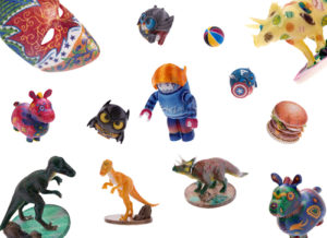
The promotional images of full-colour models certainly look impressive, but how useful is this going to be? There are limitations here. Firstly, the process only works with PLA and XYZ’s proprietary PLA at that. PLA is a popular material, easy to print with and relatively cheap, but it’s not appropriate for all uses. Then there’s the “inkjet” colouring system, anyone that’s put an inkjet printed poster in their window will know that the Sun will make short work of those vibrant colours; will the same happen with these prints? This is also FDM technology, with the same limitations of all FDM prints – limited detail, the need for supports on overhangs, etc.
One good application for this technology is likely to be in character and human modelling (and it can be no coincidence that the majority of the models shown in the above image are animals/characters). 3D prints of human beings, both head only and full body are becoming increasingly popular and being able to apply full colour to those prints is likely to only increase their popularity. It will also be useful for game/CGI designers who will be able to show a full-colour version of their creation to hold in the hand without the need for a long and complex painting process.
However, at €3,500 (price as at September 2017), this printer is in the same bracket as the Ultimaker 3 and Form 2 machines and unless there’s substantial demand (I have yet to be asked, even in a casual enquiry, about full-colour printing), it’s debatable how sensible a business purchase this will be.
So you’ve got an idea that’s going to change your life, make you a millionaire and solve the world’s problems. That’s great, but although 3D printing is pretty amazing, there are limitations and your design is key to getting good print quality.
The most common type of prosumer 3D printing is usually referred to as FDM – Fusion Deposition Modelling. It’s really a description of the process, which involves successive very thin layers of plastic being deposited one on top of the other to build the model. There’s a good explanation of it here. FDM is (relatively) quick, cheap and effective, and print quality is increasing all the time as the technology rapidly evolves, but its weakness is in its very nature.
Consider a simple sphere. There’s not really any simpler object, right? It’s a single smooth surface, no complex details, no fancy designs, but spherical surfaces can be a nightmare for FDM printing. The problem lies in the process of printing by layers. A true sphere resting on a surface has only a tiny, tiny point of contact with that surface, so the very first layer put down in printing is equally tiny. The next layer is larger so it has nothing to sit upon at the edge, so the very edge tends to sag down. This happens on the next, and the next, and the next layers until the side of the sphere becomes more vertical and the “next” layer has something beneath it to print upon. The upper surface of the sphere will print fine because the size of the layer is reducing and there’s always material beneath to print upon. So, trying to print a sphere almost always ends up with a lovely top surface and a less than lovely lower half.
A sphere is, therefore, a good example of the biggest drawback with FDM, each new layer needs something beneath it to print successfully. This drawback is not as big as it sounds as FDM can print some quite surprising overhangs, and it can “bridge” gaps quite well (for example, the upper part of a rectangular hole in the side of a box), but when designing your model, you should always try to create parts that avoid overhangs and allow for this drawback. Sometimes the simple solution is to invert the model or print it on its side, and it’s possible to use “support material” (essentially “scaffolding” for the print that is extruded along with the main model), but sometimes it’s just a case of cutting the model into different sections.
So, when you’re designing your model, try to think not only about how it will work for your project but also how printable it’ll be. The easier the model is to print, the more likely it is that your prints will be high quality and will be fit for purpose.