Building
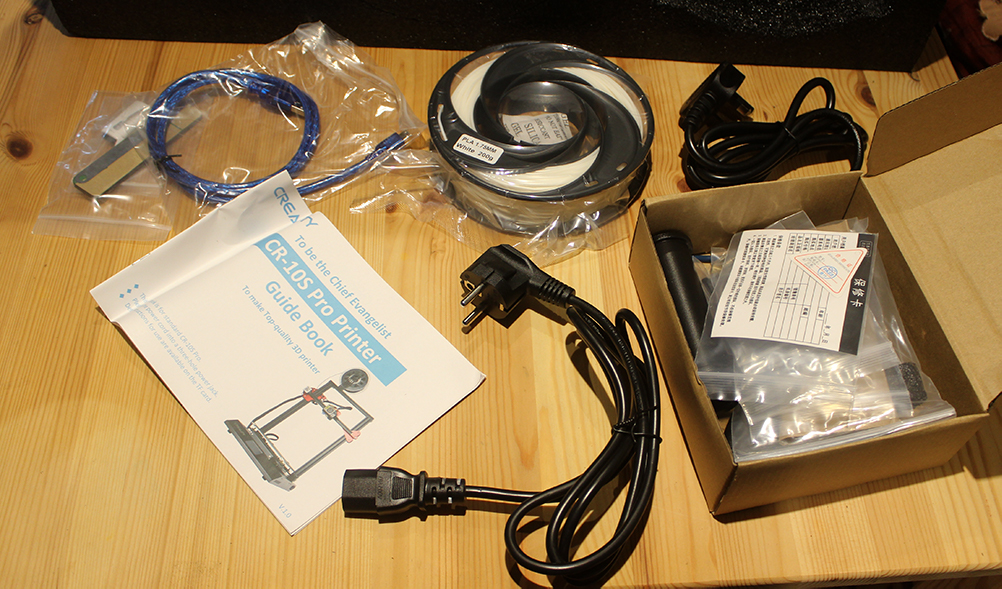
You probably won’t need any of your own tools to assemble the CR10S-Pro as the little box that was fitted in the packaging contains all the tools you should need – and some you don’t (at least not for the build itself). The build itself really only needs two Allen keys, one larger one for the gantry to base bolts and another for the filament reel holder.
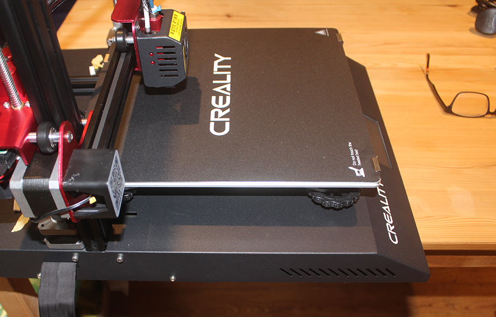
I knew from other online videos that pretty much the only “building” necessary for the CR10S-Pro is to attach the “gantry” to the main base. This requires two bolts each side to be screwed “up” from the bottom of the base into the bottom of the gantry uprights. Sounds simple, and all the videos I’d seen made it sound like it was, but it’s really not that easy.
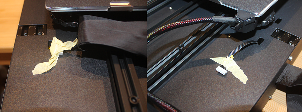
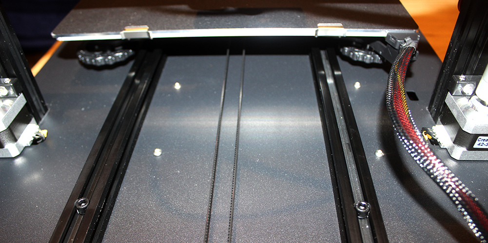
Before you attempt to fix the gantry you’ll find two cables taped to the base. These are taped quite close to where the base of the gantry fixes and would likely foul it if left where they were so I pulled some slack out and re-taped them further away. The original taping was a bit neater than it looks in the photo below, that’s the result of my fiddling…
The problem with the gantry bolts is that they’re 25mm long but the base is a lot thicker than that so it looks like you’ll be pushing the bolts up into a void where, inevitably, they’ll fall off the Allen key and you’ll need to remove the base to retrieve them. Fortunately, this isn’t the case. There are guides inside the case to stop this, but in my instance they weren’t very well aligned to the holes on the top and it took some fiddling and quite a lot of swearing to get the threads to poke clear of the holes. The holes in the base are not threaded so you can simply push the bolts until they’re a little proud and then the spongy guides seemed to hold them in place quite well.
You now have to hold the gantry in place while getting these bolts to bite into the threaded holes in the base of the gantry pillars. This really isn’t easy with only one person but I found that by hanging one side of the base off the edge of the table and with another bout of swearing it was possible. It sounds like a real pain but I’d estimate it was no more than 10 minutes in total to get both sides screwed down tight, and that included the discovery period, so having read this, you should do better.
A quick word of warning, in my case the hot-end crossbar was screwed right down to the bottom of the gantry and the nozzle was actually touching the bed when I first tried to assemble the pieces. Had I screwed the bolts in tight I would probably have drilled a nice hole in the centre of the bed so make sure you manually turn the z-axis leadscrew(s) to “raise” the nozzle a decent distance before fixing the gantry.
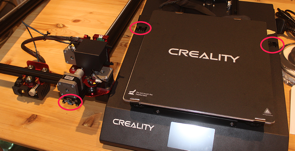
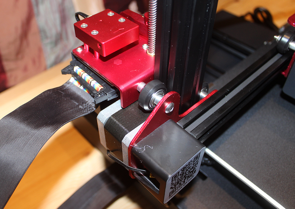
Once the gantry is tightly fixed, you can now connect up the z-axis motors using the cables you taped clear earlier. Note it’s a lot easier to do this if you push the print bed out of the way.
You’ll also need to attach the cable for the x-axis motor, which should be dangling close to its socket.
You can then attach the ribbon cable to its socket close to that motor. If you’re not familiar with ribbon cable sockets, note that you may need to push the small clips “outwards” to enable the plug to seat home, then push them back to hold it in place.
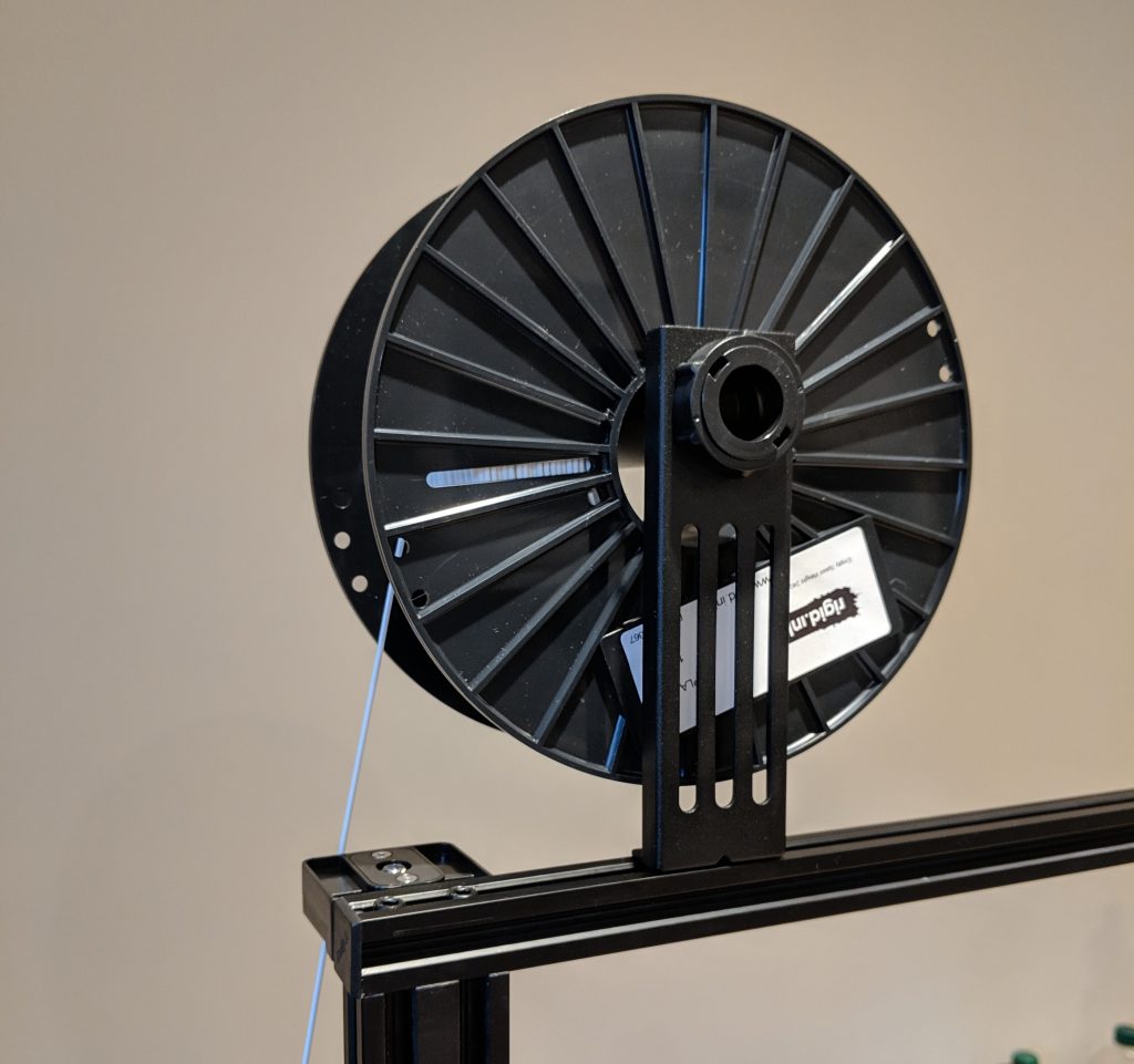
The last piece of assembly is the filament holder. This comes in three parts in the box, an upright, a rounded bar to hold the filament and a nut to secure the bar to the upright (it’s there somewhere, look for it). The holder is attached to the top crossbar by two small bolts and special nuts that need to align “front to back” on their long axis. This is kinda tricky as they want to align side-to-side which just means the holder falls off the frame. I found some poking with a small screwdriver (there’s one supplied for other purposes) gets them into place.
Note two things about this filament holder. First – the filament bar should be pointing towards the back of the printer. This seems counter-intuitive when you see the hot end at the front of the gantry, but the filament is fed into the run-out sensor at the back. Second, the filament holder needs to be fixed to the left of the printer as you look at it from the front (i.e. the same side as the x-axis motor. The way the filament feeds into the run-out sensor is less than ideal (more on this later) and getting the filament as far to the left as possible eases this problem.
With everything connected up plug it into the mains and you’re ready for setup!